A 60W solar street light can be a practical option for community roads, residential streets, secondary roads, rural routes, and parking areas, but its suitability cannot be decided from wattage alone. Pole height, road width, setback, spacing, LED efficacy, lumen output, optical distribution, uniformity, and nighttime control all affect the final lighting result.
This is particularly important for community roads because road geometry can vary considerably. A narrow residential lane with low-speed traffic requires a different lighting layout from a wider community collector road carrying vehicles in both directions.
For project buyers, the best process is to define the road first, select an appropriate optic and mounting arrangement, and then verify the proposed 60W luminaire through photometric calculation.
Use 60W as a Power Class, Not a Complete Lighting Specification
Rated wattage tells buyers how much electrical power the LED luminaire uses under its defined operating condition. It does not specify the amount of light reaching the road.
Inbrit currently positions its 60W solar street light category for applications including secondary roads, residential streets, parking areas, and rural projects, with 6–8m identified as a typical mounting-height range. The actual configuration remains project-dependent.
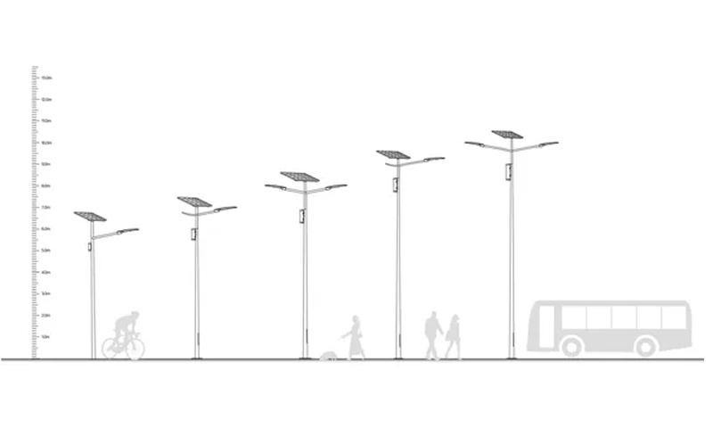
Before using this range, buyers should still check lumen output, efficacy, optic type, road geometry, and required photometric performance.
Two 60W luminaires using different LEDs and optical systems can create very different roadway results.
Start With Community Road Width and Function
The first design input should be the actual road cross-section.
Useful information includes carriageway width, lane quantity, sidewalks, bicycle lanes, parking lanes, shoulders, drainage areas, and the proposed location of each pole.
A narrow residential route may be illuminated effectively from poles on one side. A wider road may require staggered poles, opposite-side installation, or another arrangement to achieve acceptable coverage.
The road function matters as well. A low-speed residential lane with occasional vehicles has different lighting requirements from a busier community access road.
Instead of requesting “60W for a 7m pole,” buyers should provide the complete road geometry and intended use.
Why 6–8m Can Be a Useful Starting Range
A 6–8m mounting range can provide useful coverage for many medium-scale road applications, but it should be treated as a preliminary reference rather than a fixed requirement.
A lower mounting height generally places the luminaire closer to the road, producing stronger local illumination but potentially requiring shorter pole spacing.
A higher installation can spread light over a broader area, but the luminaire is also farther from the road surface. Optical distribution and available lumens therefore become increasingly important.
The design should balance coverage, uniformity, glare, pole quantity, structural requirements, and maintenance.
Road Width and Mounting Height Should Be Evaluated Together
A 7m pole beside a 6m road creates a different lighting geometry from a 7m pole beside a 10m road.
The wider roadway requires the luminaire to send useful light farther laterally while still maintaining adequate illumination on the near side.
If the selected optic is too narrow, the far edge may remain underlit. If it is excessively broad, useful lumens may be wasted beyond the target area or create additional glare.
For this reason, mounting height should never be finalized without considering the actual width that the optical system needs to cover.
Pole Setback Changes the Effective Road Width
Street-light poles are not always positioned directly at the curb.
Sidewalks, underground utilities, landscaping, drainage channels, safety zones, and property boundaries can force the pole several meters away from the carriageway.
This setback increases the horizontal distance between the luminaire and the far side of the road.
An optic that performs well when the pole sits next to the curb may no longer provide the same result after a significant setback.
Arm outreach can move the luminaire closer to the carriageway, but a longer arm also influences pole loading and structural design.
The photometric model should therefore use the actual luminaire coordinates rather than assuming that the pole is always installed at the road edge.
Spacing Should Be Determined by Uniformity, Not Maximum Reach
One of the most common project questions is how many meters should separate two 60W solar lights.
There is no universal spacing value.
Increasing spacing reduces pole quantity and civil work, but excessive distance can create dark zones halfway between adjacent poles. Shorter spacing improves overlap but increases equipment and installation cost.
The correct spacing depends on mounting height, optics, lumen output, road width, pole arrangement, setback, average lighting target, minimum lighting level, and uniformity.
The design objective should be continuous useful illumination rather than the maximum distance at which light remains visible.
Optical Distribution Can Matter More Than Additional Wattage
If a 60W layout does not illuminate a road effectively, increasing LED power should not be the first automatic response.
The project should check whether the selected optic is placing light in the correct directions.
Roadway optics can distribute light longitudinally along the road while sending sufficient illumination laterally across the carriageway. A less suitable beam may concentrate excessive light under the pole and provide weak overlap between adjacent fixtures.
Changing optical distribution can therefore improve roadway performance without increasing nighttime energy consumption.
This is especially valuable for solar lighting because every extra electrical watt also increases the energy that must be stored and regenerated.
Use Photometric Files to Compare Different Optics
Professional road-lighting design should use the photometric file for the exact luminaire configuration being proposed.
The U.S. Department of Energy's exterior lighting procurement guidance emphasizes luminaire efficacy and photometric performance when evaluating exterior LED equipment.
An IES or equivalent photometric file can be imported into lighting-design software together with road dimensions, pole height, spacing, and luminaire position.
Different optical options can then be compared using the same 60W power class to determine which distribution provides the best road coverage and uniformity.
Average Lux Alone Can Hide Dark Sections
A lighting calculation can produce an acceptable average illuminance while still containing weak areas.
For example, very bright regions directly under each pole can raise the numerical average while the midpoint between poles remains relatively dark.
Minimum lighting level and uniformity help reveal these problems.
Community roads benefit from consistent visual conditions because drivers, cyclists, and pedestrians move continuously through the illuminated area rather than remaining directly beneath the poles.
Project approval should therefore evaluate the full photometric layout rather than relying only on one average-lux number.
Single-Side and Staggered Layouts Produce Different Results
A narrow community road may use all poles along one side. This can simplify civil work and electrical or solar installation, but the optic must provide sufficient lateral reach.
For wider roads, staggered poles can improve coverage by alternating the luminaire positions between opposite sides.
Another option is opposite-side placement, where paired poles illuminate the road from both directions.
Each arrangement changes pole quantity, foundation locations, optical requirements, and project cost.
Rather than choosing the arrangement from aesthetics alone, EPC teams should compare the photometric performance and complete BOQ.
Higher Lumen Output Does Not Automatically Mean Better Comfort
Increasing lumen output can raise road illuminance, but excessive brightness or inappropriate high-angle light may also increase glare.
A community street should provide enough light for its intended users without creating unnecessary discomfort for drivers or excessive spill toward nearby homes.
Optical control is therefore particularly important in residential environments.
Where buildings sit close to the road, buyers may also need to review backlight and unwanted light outside the carriageway rather than optimizing only pavement lux.
Dimming Should Follow Real Community Traffic Patterns
Community roads often experience their highest activity during the early evening, followed by substantially lower traffic after midnight.
A 60W luminaire can therefore use a staged control profile where appropriate.
For example, it might maintain full or relatively high output during busy hours and reduce power during quieter periods while maintaining the minimum lighting performance required by the project.
DOE notes that adding advanced controls to exterior lighting can provide additional energy savings beyond luminaire efficiency alone.
For solar systems, those savings also reduce battery discharge and the amount of energy the photovoltaic module needs to restore the following day.
Do Not Extend Pole Spacing by Using Excessive Wattage
A project can sometimes appear cheaper if fewer poles are used with higher-power luminaires. However, increasing output cannot always compensate for excessive spacing.
If the optical distributions from adjacent poles no longer overlap effectively, increasing brightness may simply make the areas around each pole even brighter while leaving the midpoint comparatively weak.
The project should therefore optimize pole spacing and optics before increasing wattage.
This also produces a better solar-energy design because unnecessary LED power increases battery and panel requirements on every pole.
Energy Autonomy Still Needs to Match the Road Design
Once the lighting design determines the approved 60W operating profile, the battery and photovoltaic system can be calculated.
A fixture operating at full output for only part of the night may consume far less than 720Wh over a 12-hour period.
Battery Wh should reflect the real dimming program, usable battery range, required autonomy, and expected temperature. Solar-panel capacity should then be selected from local solar conditions and the required battery-recovery strategy.
Lighting design and energy design should therefore happen sequentially: first determine how much light the road needs, then calculate how much energy that approved lighting schedule consumes.
What Should Buyers Provide for a 60W Road-Lighting Proposal?
Useful project inputs include country or coordinates, road width, lane quantity, sidewalks, pole position, proposed mounting height, arm outreach, target spacing, road function, required lighting criteria, operating hours, dimming requirements, autonomy target, and environmental conditions.
The supplier should then provide the proposed luminaire, optical distribution, photometric calculation, pole arrangement, battery Wh, photovoltaic capacity, and controller schedule.
This gives the purchasing team a complete technical basis for comparing different 60W proposals.
60W Solar Street Light for Community Roads FAQs
What pole height is suitable for a 60W solar street light?
Inbrit currently identifies 6–8m as a typical range for its 60W category, but actual mounting height should be verified against road width, optics, lumen output, spacing, and the required lighting performance.
How far apart should 60W solar street lights be installed?
There is no fixed spacing. Mounting height, road width, optics, lumens, pole layout, setback, minimum illuminance, and uniformity all affect the correct distance.
Is 60W enough for a community road?
It can be suitable for many community, residential, secondary, and rural roads, but the final decision should come from a photometric calculation using the actual site geometry.
Is more lumens always better?
No. The luminaire needs enough useful light to meet the road requirement, but optics, glare control, uniformity, and unwanted spill are also important.
Can changing optics improve lighting without increasing wattage?
Yes. A better-matched optical distribution can place more of the existing lumen output on the intended road area and improve overlap between poles.
Should battery sizing be completed before pole spacing is finalized?
Ideally, the photometric design should define the approved lighting and dimming profile first. Battery and photovoltaic sizing can then use the resulting nightly Wh consumption.
Conclusion
A 60W solar street light can provide a practical solution for many community roads, but its effectiveness depends on much more than nominal wattage. Road width, mounting height, pole setback, spacing, lumen output, optics, uniformity, glare, and pole arrangement determine whether the available light is distributed effectively.
For B2B projects, the preferred process is to model the actual road using the exact luminaire photometric data and compare optical and spacing alternatives before finalizing the solar-energy system.
Once the lighting layout has been approved, the resulting nighttime Wh can be used to size the battery, panel, and controller. This creates a coordinated road-lighting solution in which photometric performance determines energy demand rather than allowing a catalog wattage to dictate the entire project.


 English
 français
 Español
 العربية
 Pilipino
 ไทย
ไทย tiếng việt
 Malay
Malay русский